
Introduction and deep dive into data storage in factories.
Introduction
This guide will cover a variety of latches (single bit storage), read-only memories (ROMs) and even a read and write sequential memory.
SR Latch
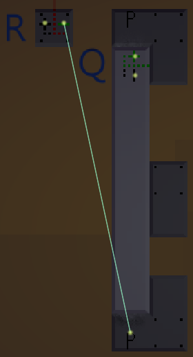
An SR latch can be constructed with 2 pistons that pushes a block back and forth in front of a sensor.
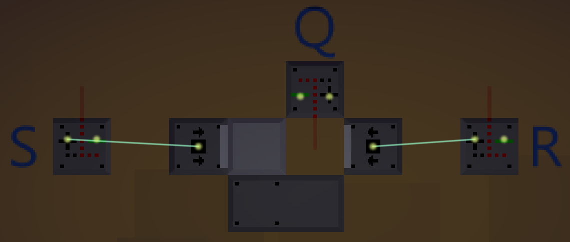
A simple SR latch made out of two pistons. The output can be retrieved from the sensor labelled Q.
In electronics, the situation where both S and R are set is considered a so called Forbidden State. What should happen when both Set and Reset are used at the same time is not defined, and due to how an SR latch is constructed in electronics, it might cause strange behaviour.
In our design above, activating the two pistons at the same time won’t cause any critical issues, but it will make our latch behave a bit strangely. If one of the pistons were already active prior to them both being active, the latch will just stay in its current state, as the “new” piston simply won’t extend. If none of the pistons are active, one piston will beat the other one in the race and activate slightly before the other. The “fast” piston is always the same one. I think it’s always the left-most piston, but I’m not entirely sure.
JK Flip-Flop
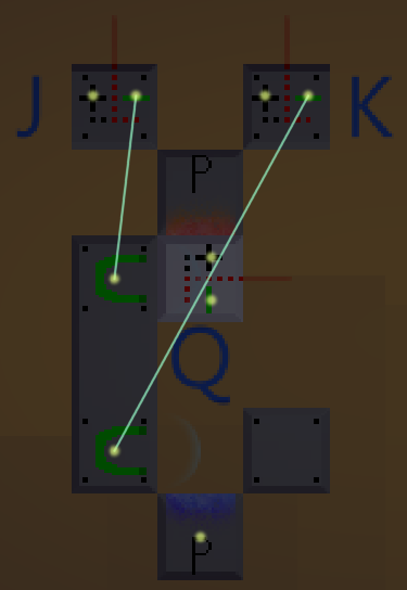
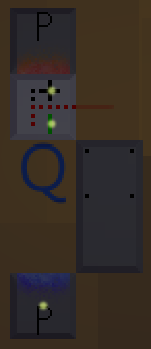
It’s surprisingly easy to build a JK flip-flop. Here are two possible designs:
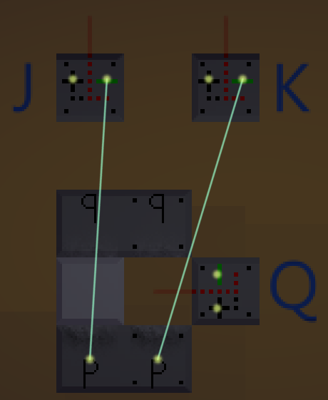
A JK flip-flop. Note that the input sensors use their negative side and that the top portal is flipped.
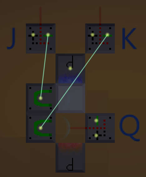
Another JK flip-flop. Note that the input sensors use their negative side.
Both the above designs are logically the same, however, I prefer the second one due to its flexibility when it comes to future tweaks, changes and applications of the JK flip-flop. Therefore, I will use the second one in this guide, or rather a somewhat tweaked version of it.
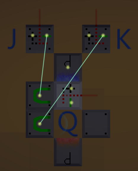
A JK flip-flop where the sensor is loose and moving.
T Flip-Flop
A T flip-flop is a JK flip-flop with just a single input.
The above flip-flop works great, sort of. If the input signal is active for more than a single tick, it will start to swap back and forth. In other words, each tick the input signal is active the state of the flip-flop will change. Although that might be what we actually want, it’s quite common that we only want it to flip once we get a new signal (an active input that follows an inactive one).
We can build a so called Rising Edge Detector (which will be discussed in the next section), but there’s no need to make things overly complicated if we can work around it. If we know that the input signal we receive will always be 2 ticks long (for instance if we always detect pieces consisting of 2 blocks) we could build our T flip-flop as shown below.
A T flip-flop that takes an extra tick to flip over.
The above design will not swap values as fast as it could. That is however easily fixed by just changing the blocks on the right, as shown in the image below.
A T flip-flop without any extra delay, but it will ignore any signals for one tick after flipping.
The same strategy used above, can also be used for JK flip-flops. Sometimes everything becomes a bit too tight to fit that one sensor you need, but we might be able to place it one step earlier. If so, we could easily add a delay to the JK flip-flop, and the delays for Set and Reset obviously don’t have to be the same length.
A JK flip-flop that takes an extra tick to Set its state but Resets as normal.
Rising Edge Detector
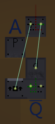
A Rising Edge Detector. The line above the Q denotes that the output is inverted.
To begin with, the sensor detects the portal in front of it. When the input (A) goes to high, the portal reactivates and the piston starts to extend. The sensor now sees straight through the portal and detects nothing on the other side. A tick later the piston has had time to extend and the sensor now detects the piston head (sensors don’t see the side of piston heads but can see the front just fine). During the tick when the portal has activated but the piston arm hasn’t yet extended is the only time the sensor detects nothing in front of it. By connecting the negative side of the sensor to whatever we need the pulse for, we now have a Rising Edge Detector.
Below is another possible design, it has some pros and some cons compared to the above design.
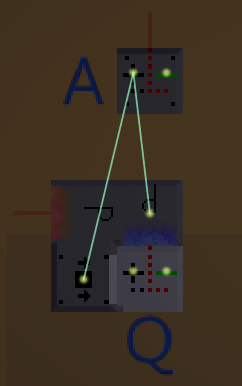
Another Rising Edge Detector design. This one seemingly more compact, but looks can be deceiving. The sensor is welded to the piston.
Although the two designs work fairly similarly, there are still a few differences between them. One is the output: it’s inverted in the first design but not in the second. This is more or less irrelevant as the sensor has both a positive and a negative side (so we can connect it to whatever we need). Another difference is how compact they are. While the second one looks more compact than the first, this isn’t actually the case. The second design requires 3 empty spots around it, making its total space bigger than that of the first design.
However, the one big difference between the two designs is the input. The first design uses both the positive and negative sides of the sensor while the second design only uses the positive side. As long as our input is just a sensor, this has absolutely no merit. However, if the input is something more complex, we wouldn’t automatically have the inverted value as well. To use the first design we would then need an instant NOT-gate (see my guide Logic Gates for more information) to hook it up.
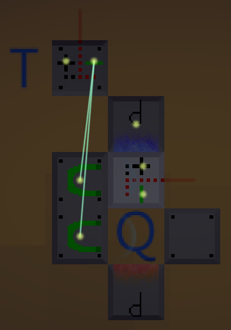
When we now have a Rising Edge Detector, we could simply connect its output to a basic T flip-flop to make a T flip-flop that only changes its value on a rising edge (when it receives a “new” signal).
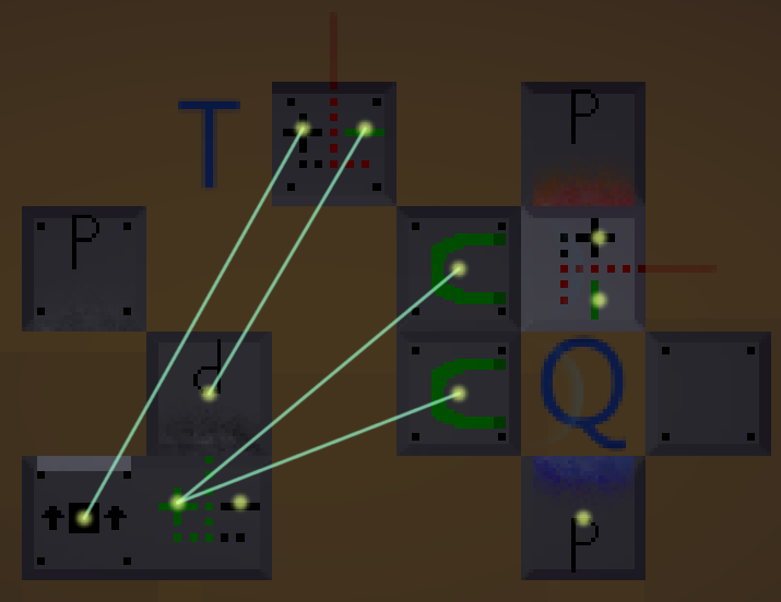
A rising edge T flip-flop. It uses the first design of the Rising Edge Detector. Note that we actually use the positive output since the flip-flop part wants a negative input to keep the magnets on.
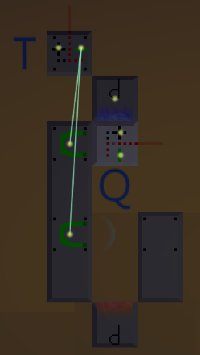
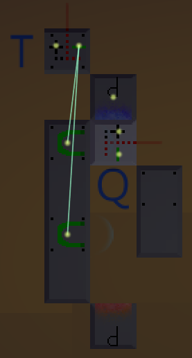
If you want to pack them together into one thing (logically the same, just more compact) you could do it as the design below.
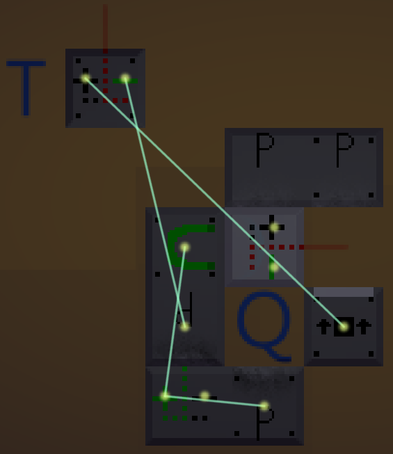
A compact rising edge T flip-flop. The core of the flip-flop uses only one magnet and instead controls the portal as well (this is a combination of the two designs of the JK flip-flop). This design also utilises the fact that sensors don’t see the side of a piston head.
D Latch
A simple D latch.
Read-Only Memory
When the Read input is received the sensor falls, detecting the blocks on the right.
The above design allows us to easily set up the memory like we want, simply by placing or removing blocks on the right-hand side. Once the sensor has fallen to the bottom it will restart but will get stuck on the magnet as it waits to be released again.
The above design can be made slightly more compact, by flipping the sensor to the other side. This forces the first block to always be set, but since we might as well connect to the negative side of the sensor we can just invert it all if needed.
A more compact version of the ROM in the previous image.
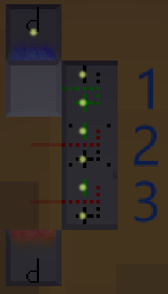
We can easily put together multiple memory units that each control different things.

3 ROMs next to each other. All of them use the same Read input.
Slow ROMs
A ROM that can be controlled in detail.
If we want to keep the compactness of the memory, we can use a different design that uses a tall pillar and controls the portal itself.
Another version of the fully controllable ROM.
Clocks
A simple clock with 1 tick spacing between its 2 tick pulses.
By returning to having fixed sensors we could easily make it control multiple things, albeit only a single tick each.
Clock that alternates between 3 different sensors.
I usually use this type of design to control the whole factory. As an example, the first tick could release magnets to move all pieces forward, the second could add a block to the output and the third could do the same, but this time only if the inputs and various latches are in the correct state, then repeat it all. That example is how I solved the “Adder” puzzle in a fast and efficient manner.
Multi-State Latches
A 3-input latch with 3 states, but only 2 possible outputs.
We can’t get more than 2 possible outputs from a sensor. However, if we need more outputs, we can simply add more sensors.
Two 3-input latches with 3 states, both with 3 possible outputs.
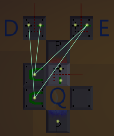
RW SAM
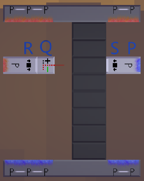
The storage bits and the read/erase arm and the write arm.
The data storage is made out of a bunch of rows, each consisting of two blocks (shown in dark in the image above). Each row is welded internally, but the rows themselves are loose and just resting on top of each other. The idea is to move these rows between two states by either pushing them to the left, or by pushing them to the right. Since they can be in one of only two positions, they will rest on the row below them, even if they aren’t perfectly aligned with that row. Each row represents one bit of data. In the image above, all bits are set to 0 since they are in their right-most state.
On either side of the data storage are the two memory access arms. These will move down in unison, analysing and changing the states of the rows as they go. Once they reach the end, they will simply go through the portals to reach the top again. The portal on the write arm (the one on the right) is connected to the portal on the read/erase arm (the one on the left). There will never be anything going through these portals. They are merely used to lock the both access arms into place when they aren’t supposed to move.
The data storage part, as shown in the image above, is not enough to construct our RW SAM. It currently doesn’t really do anything. Before I introduce the logic unit, let’s take a look at what the inputs and outputs of the data storage do:
- Set (S): Sets the current bit.
- Reset (R): Resets the current bit.
- Movement (P): Moves both arms down (one spot for each tick this signal remains high).
- Bit Output (Q): The state of the current bit (this is however not the final output of the whole SAM).
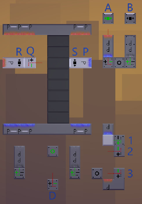
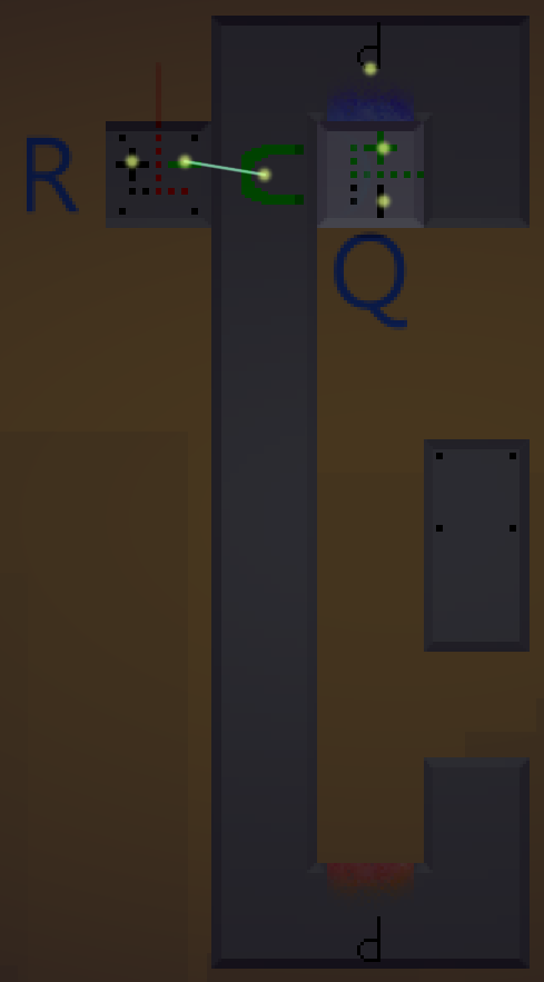
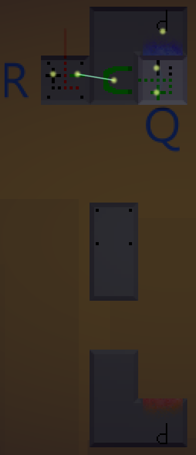
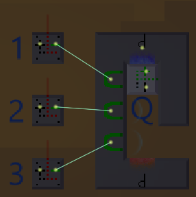
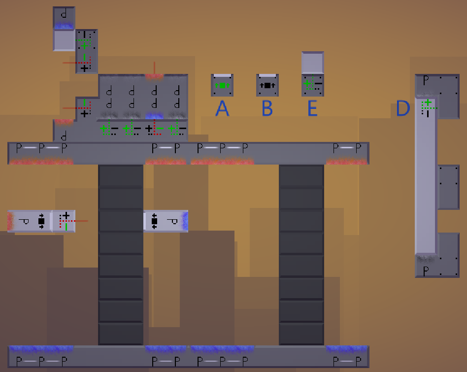
The full RW SAM, purposely spread out to make it easier to see.
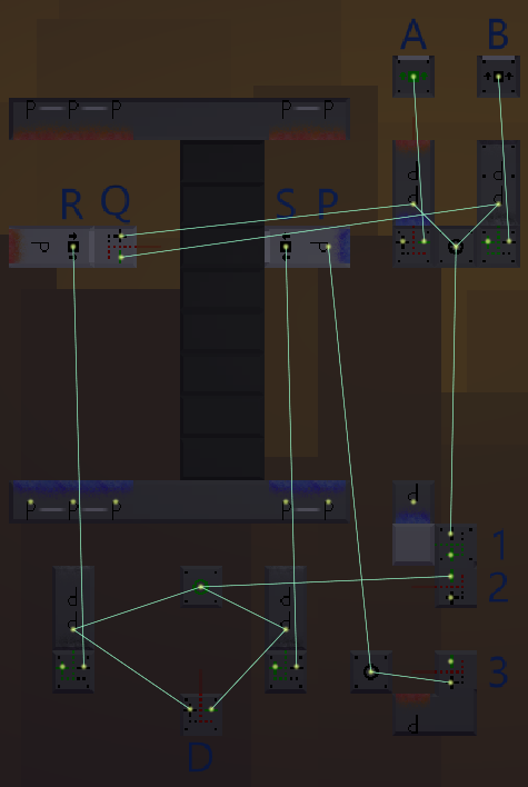
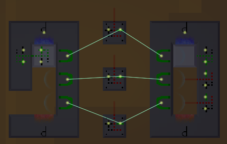
The wires of the full RW SAM.
The additional alphanumerals describes the following:
- Output, low (A): A signal when an unset bit is read (piston just used for demonstration).
- Output, high (B): A signal when a set bit is read (piston just used for demonstration).
- Data input (D): The data to be written to the memory.
- Read state (1): Read the bit at the current location
- Write state (2): Write the input data into the memory
- Move state (3): Move the access arms
The logic of the RW SAM uses some instant AND-gates. For more information on how they work, see my guide Logic Gates.
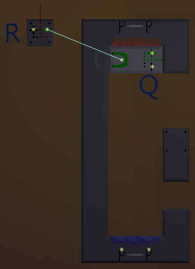
The Read State
Since the output Q will always read the bit, we use some AND-gates to only do it while we’re in the read state. While we’re writing to the memory or moving the access arms, the read data might not reflect the value we want, which is why we do this. Also note that the two outputs A and B are not each other’s opposite. Not always anyway. When we’re not in the read state, they are both inactive. In the read state, one will be active and one will be inactive.
The Write State
In the same manner we had to use AND-gates while reading, we also have to use them while writing data. If we don’t, we won’t be able to read or move properly, as one of the access arms would be trying to write all the time (which arm would depend on the input D). The reason there’s a gap after this state is because of the time it takes for a piston to extend. The Write State has to take 2 ticks to allow for the piston to return to its retracted state.
The Move State
Once a read and a write has been done, we simply send a 1 tick pulse to portal P to move everything down to the next bit.
Together these 3 states lets the memory follow a simple 4 tick cycle: read, write, (wait), move, read, write, (wait), move, etc. The value that has been read is the value that was written there the last time, and the value written is the value currently on the D input.
Writing to the memory does of course overwrite what’s already there. One could easily add an input signal E, that makes the memory only write while that signal is high (use an AND-gate to only send the Write State signal if there’s a signal on E).
The memory in the example uses 8 bits, but more bits could easily be added by simply adding more rows.
I wouldn’t really build the memory like it is shown in the example, all spread out with a ton of extra nodes. I made another version, putting all the logic together in one place. I also added the input E, which is required to be set for writing to occur. On top of that I increased the capacity to 16 bits. You could do this by just stacking more bits on top of each other, but I added another stack. The portals are linked to the portals on the other stack. Finally I connected the D input to a 7 bit Slow ROM, just for testing that it worked, which it did.
Second version of the RW SAM.
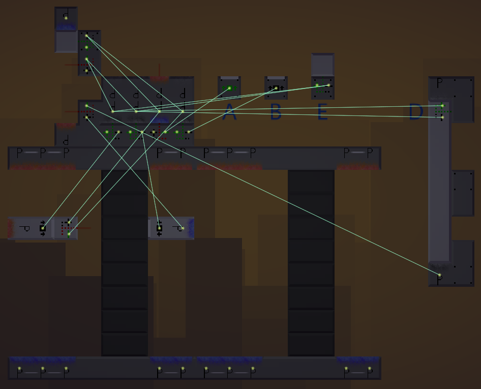
The wires of the second version of the RW SAM.
Real Puzzle Examples
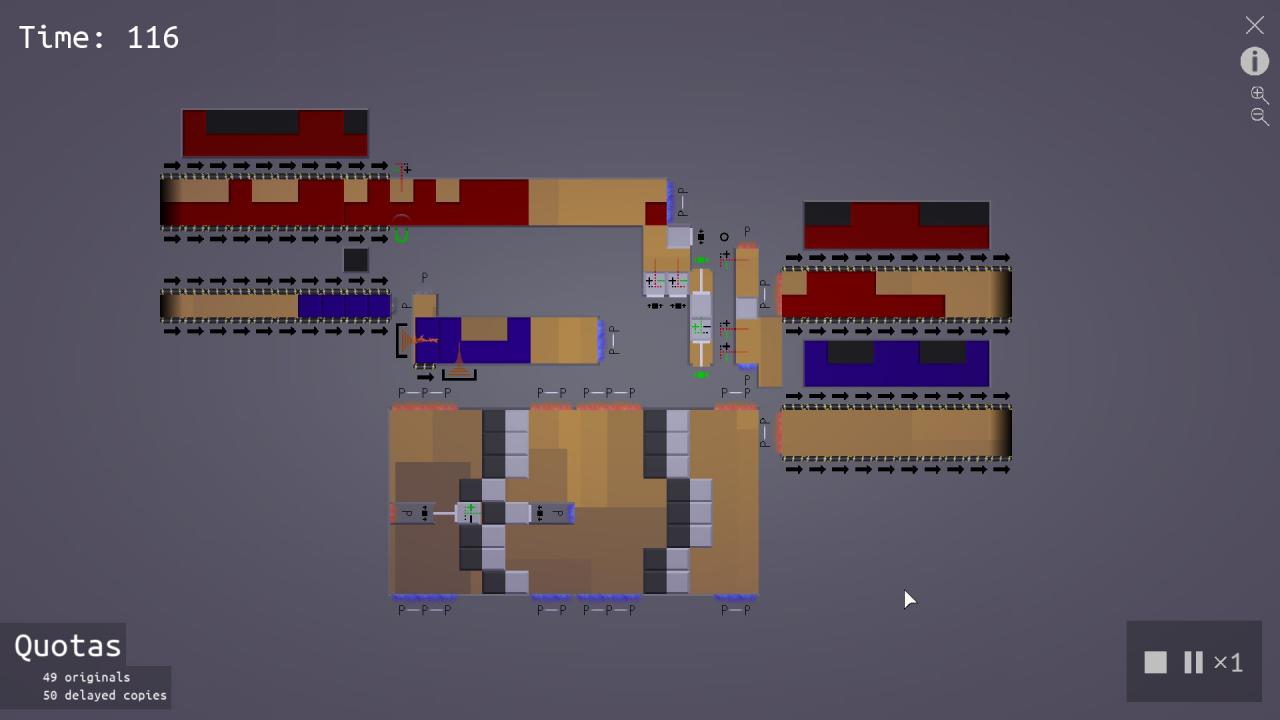
Nortal switcher of “Switcher” blindly swapping using 5 ROMs.
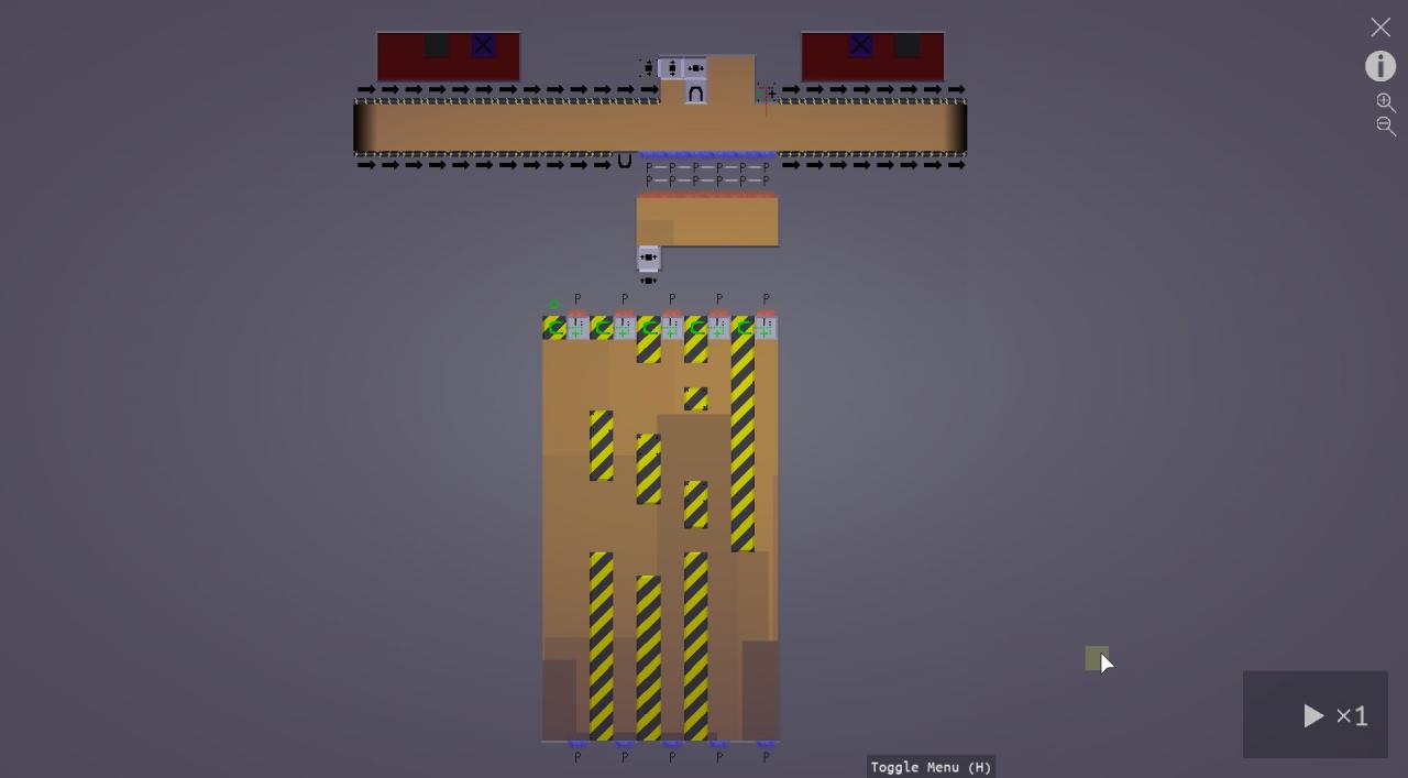
16 bit RW SAM used to solve “Memory”.
Thanks to Swen V for his great guide, all credit to his effort. you can also read the original guide from Steam Community. enjoy the game.